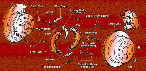
General diagram of a rear
disc brake setup. Source: unknown
Before You Begin.
The disc brake conversion described in
the article below was performed on a stock 1994 Ford Explorer Sport.
Therefore, this article does not take into consideration any modifications
or different model years. The most difficult part of this conversion
was dealing with the longer left parking brake cable. (A lifted Explorer
may benefit from the longer cable because in most cases, a lift kit will
need longer parking brake cables). I obtained all the pieces necessary
for this conversion from an individual who was planning to install the
brakes on a Ford Ranger, therefore, I did not experience removing the disc
brake setup from a donor truck. My recommendation would be to make
certain to obtain all the pieces necessary for the conversion. If
you dont, youll be spending time later trying to hunt down the necessary
parts to complete the installation. For additional assistance, consult
the diagrams and pictures in a Ford Explorer repair manual.
Parts List:
1) Mounting brackets and backing plates
(Right and Left) with mounting bolts (8 total).
2) Calipers (Right and Left). If
you decide to go with new calipers (recommended), youll need the old ones
for cores.
3) Disc brake pads (Right and Left).
In some cases, these will be needed for cores.
4) Rubber caliper hoses. (Right
and Left).
5) Bolts to secure calipers to mounting
brackets (4 total).
6) Steel axle housing brake line with
mounting bracket and bolt.
7) Rotors (Right and Left).
8) Parking brake cables (Right and Left)
with all attaching hardware, retaining springs, and hangers.
9) Intermediate parking brake cable.
- 2 Door Ford Part Number: F5TZ-2A793-A
- 4 Door Ford Part Number: F5TZ-2A793-B
10) Parking brake pedal assembly (optional).
11) Parking brake hardware including:
shoes, hold down springs, hold down pins, adjuster screws, return springs,
and lever assemblies. Depending upon the year of the donor vehicle,
the design for the parking brake mechanism will be different. Note:
New shoes are expensive and are not available from aftermarket parts suppliers.
Be sure that the shoes have adequate lining thickness, or be prepared to
spend around $100 to get a new set from a Ford dealer.
12) New gasket for differential cover.
13) Anaerobic gasket sealer
14) Steel strap. (To make brackets
to secure the rubber caliper hoses)
.
Safety First!
Park the vehicle on a level surface and
block the front wheels to prohibit the vehicle from rolling.
Raise the rear of the vehicle, support
it on jack stands and remove the rear wheels. Also remove the spare
tire for more working room.
Disassembly
Place an oil pan under the rear differential
and remove the ten bolts securing the differential cover and drain the
differential fluid. Clean off the old gasket material from both the
differential housing and the differential cover. Tip: Wipe
down the contact surfaces on both the differential housing and the differential
cover with brake cleaner to remove oil from the surfaces. It is absolutely
necessary to have a clean surface to prevent the new gasket from leaking
in the future.
Remove the drum assembly and carefully
clean any dirt surrounding the axle shaft seal. Note: Brake
cleaner works well for this task.
Remove the differential shaft lock bolt
and the differential pinion shaft. Note: Rotate the differential
slightly in order for the pinion shaft to slide out easier.
Press each of the axles towards the center
of the vehicle to gain access for the removal of the C-clips. Remove
the C-clips with a pair of needle nose pliers.
Carefully remove the axles from the housing.
Wipe any excess fluid from the shaft with a clean shop towel as the axle
is being removed.
Remove the steel brake lines from the old
drum brake cylinders. Also remove the rubber brake line that connects
the housing brake line and the rear brake line feed. Finally, remove
the bolt clamp bolt from the top of the differential housing that holds
the steel brake line in place and remove the steel brake line from the
vehicle. Place a container under the rear brake line feed to catch
any fluid that drips out.
Disconnect the parking brake cables from
the intermediate cable. Remove all springs and plastic connectors
that hold the parking brake cables in place. On the passenger side,
remove the bolt from the shock mounting plate to remove the bracket.
Remove the four backing plate mounting
bolts from each side of the vehicle and remove the old drum brake assemblies.
Be careful to not get any dirt or debris inside the differential housing.
A good tip is to plug the axle tubes with a clean disposable shop towel.
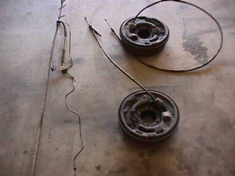
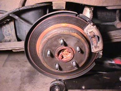
Original drum brake setup
complete with parking brake cables and steel brake line.
Reassembly
Bolt on the new disc brake mounting brackets
and backing plates in the opposite manner as the old drum setup was removed.
Reassemble the parking brake assembly by
attaching the hold down pins, hold down springs, adjuster screws, and return
springs to the backing plate. Note: It is easier to do this
step with the axles removed from the vehicle.
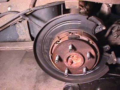
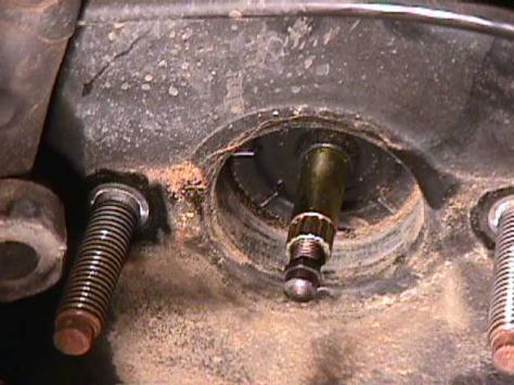
As you can see, it is very difficult to
install the parking brake assemblies with the axles installed in the housing.
Reinstall the axles into the axle housing
and reinstall the axle C-clips, differential pinion shaft and differential
shaft lock bolt in the same way as they were removed.
Reinstall the differential cover with a
new gasket combined with an anaerobic sealer. In my experience, the
anaerobic sealer combined with a new gasket provides the best seal.
I have found anaerobic sealer only at NAPA auto parts. Its a little
pricey but the results are worth it.
Follow the procedure in most repair manuals
for the torque sequence of the differential cover.
Install the rotors over the axle and parking
brake assemblies. Make sure to have the rotors turned before they
are installed. Even if a donor truck has very low miles, such as
my case, the rotors can become very badly warped. If the rotors are
brand new, I would still have them turned. In other words, make sure
the rotors are true before installing them on the vehicle.
Install the caliper assemblies with pads
onto the mounting brackets. Tighten the two bolts that hold the caliper
in place on each side of the vehicle. Be sure not to over tighten
these bolts, they can be broken easily if not careful.
Attach the rubber caliper brake lines to
the calipers. Attach the rubber brake hose from the left caliper
hose to the main brake line feed. Attach the steel housing brake
line to each caliper and replace the mounting bolt that secures the bracket
on top of the differential housing.
Note: The 95 and newer axle housings
have a mount to secure the rubber caliper hose, however the 94 and earlier
housings do not have this mount. In this situation, I cut a piece
of strap steel about 2 inches, drilled an offset hole, and tacked welded
this mounting bracket to the axle spring perch. From here I was able
to secure the rubber caliper hose. See the picture below.
The steel strap can be obtained from most
hardware stores. If you do not have access to a welder, an exhaust
shop can tack weld the bracket on later.
Attach the disc brake parking brake cables
to mounting brackets and attach the end of the cable to the parking brake
levers. Finish mounting the cables to the original locations using
the original hardware.
Attach the intermediate parking brake cable.
Double check all brake line connections
to ensure they are tight.
Completed left side assembly.
Install the tire and wheels.
Before lowering the vehicle, adjust the
parking brakes by inserting a flat-headed screwdriver into the adjuster
hole on the backside of the mounting plate. Rotate the screw to spread
the parking brake shoes. Be sure not to spread the shoes too far
causing the parking brake to be too tight.
Lower the vehicle off of the jack stands.
Remove the fill plug on the differential
housing and fill the differential with recommended gear oil. (A level
surface is necessary for this step)
Fill the master cylinder with new brake
fluid.
Bleed all four brakes, starting with the
one furthest from the master cylinder working towards the closest.
(Right rear, left rear, right front, left front). Be absolutely certain
that the fluid level of the master cylinder does not get too low.
After the brakes have been bled, remove
the 9/16 nuts that mount the master cylinder to the power brake booster.
(Do NOT loosen any brake lines). This will expose the pushrod for
the master cylinder. In order to maintain a good pedal feel after
the conversion, the rod must be adjusted to push further into the master
cylinder. With the closed end of a 9mm box wrench, hold the pushrod,
and with a 7mm box wrench adjust the nut on the end of the pushrod.
This procedure is trial and error and will require you to test drive the
vehicle in order to get a desired pedal feel. See picture below.
Final Note
The braking power on the new disc brake
setup is very impressive. Im estimating a 50% increase in braking
power over a stock setup. This is with carbon metallic front pads
and rear disc brakes. Brakes are not an item on your vehicle to be
overlooked! Be sure to recheck all brake lines for leaks after the
conversion is complete as well as readjust the parking brakes after about
500 miles of driving. I also found it necessary to readjust the master
cylinder pushrod after about 1000 miles of driving.
If anyone has any comments, questions,
concerns or additional information about this conversion, please feel free
to email me so we can update this documentation. brett@explorerforum.com
These tips are not endorsed by Ford. They are provided
for use at your own risk and discretion.
|
|