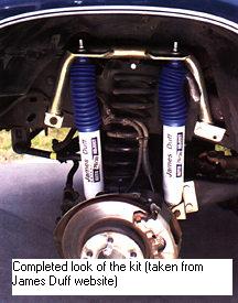
James Duff Dual Shock
Kit
PN #5260 for BII, 89-94
Ranger, 91-94 Explorer
Tools:
¾ socket and wrench
14mm socket and wrench
15mm wrench
18mm socket
3/8 and ½ drill bit
Drill
Sawzall
9/16 wrench
Torque wrench
Jackstands
4 C-clamp
Black spray paint
Punch
Time = 2 hours per-side
Tips = The sawzall is much easier
than bending metal. Also test fit all pieces before doing any cutting
or drilling, then do it again to be sure. After any cut or hole drilled,
be sure to paint the exposed metal to keep rust away.
Benefits = Dual shocks will absorb
more energy than a single shock. This means a more controlled ride
and smoother ride for occupants. With 2 shocks, heat and fade will
be less of an issue over with hard use by spreading the work load between
the dual shocks. Reduction of body roll and elimination of common
tire cupping and scissoring found on independent front suspensions.
Lastly you can choose to remove the sway bar since the dual shocks will
help eliminate that and get added articulation with greater independent
front action from the TTB.
Instructions(from the Duff instructions
plus personal input)
1. Jack up the vehicle, place jackstands
under the radius arm brackets and remove wheels with ¾ socket.
I put the stands on the frame behind the radius arm brackets and I left
the jack under the radius arm for extra support.
2. Remove the original shocks on both sides.
The top is a 15mm nut, and the bottom is a 18mm nut. Once the shock
is removed, cut the upper rubber bushings from the factory shock tower.
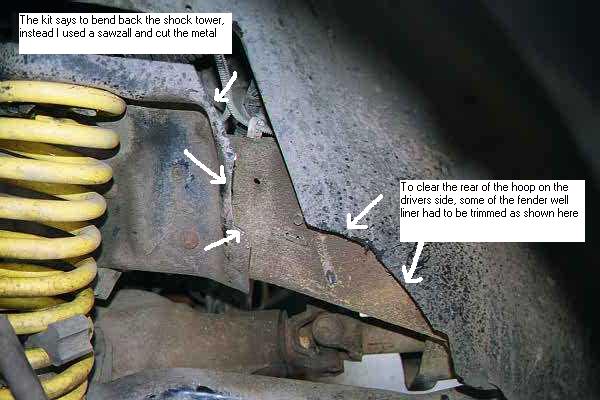
3. The directions tell you to bend
the shock tower at this point. I used a sawzall and trimmed the towers
along the lines that the directions stated. Also the factory plastic
wheel liner needs to be trimmed on the drivers side. Test fit the
hoops, measure and check before doing any cutting.
4. On the drivers side: remove
the lowest bolt in the steering box and attach the forward bracket of the
left side hoop loosely in place using the original bolt.
*on vehicles equipped with an engine
stabilizer, it is necessary to remove the bottom bolt from the lower bracket.
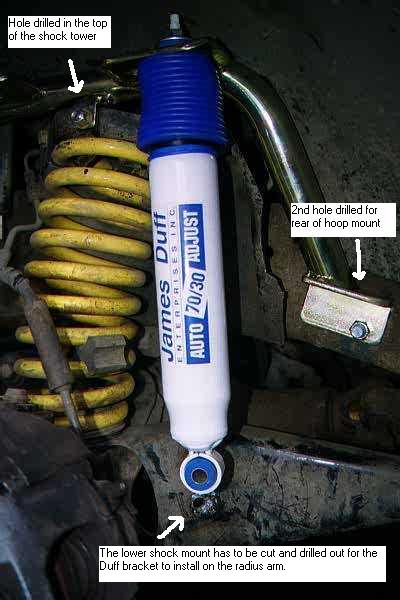
5. Align and clamp the small tab in the
center of the hoop to the coil tower. Insure that the hole in the
tab is centered vertically for a strong connection. Punch the metal
to give the drill a place to start. Remove the hoop and drill the
hole with the 3/8 bit. Then put the hoop back and bolt loosely in
place behind the shock tower ( I had to mount it in front for clearance
with the engine stabilizer bracket) with the 3/8 x 1 bolt and nylon lock
nut.
6. At the rear, check the location of the
proportioning valve on the backside of the frame. Then drill the
½ hole using the hole in the hoop as a guide. Bolt the rear
of the bracket loosely with a ½ x 1 ½ bolt and nylon lock
nut.
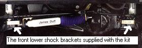
7. Remove the factory lower shock mount
with the sawzall and drill out to ½. Replace it with the
extended length bracket and bolt provided. Zip tie the brake line to the front
coil spring to keep from rubbing on the shock.
8. Install both shocks to the top of the
hoop in the forward most and rear most holes. Be sure that you install
the metal bushing in the bottom eye of the shock before installing them
and the shock boots. Dont use the inner 2 holes on the hoops to
mount the shocks, but rather the outer most holes.
9. Install the lower end of the shock in
the lower mount with the 100x12mm bolt. From outside in:
- Bolt
- Lower shock bracket
- Shock
- Washer
- 12mm spacer
Now put that assembly through the new
hole in the radius arm bracket. On the back side secure with a lock
washer and nut then tighten.
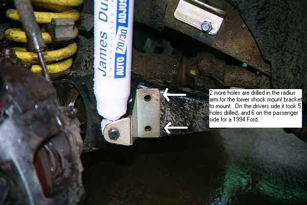
10. Drill 2 more ½ holes in the
radius arm using the lower shock mount for a guide. When done, you
will need the black colored backing plate on for the back side of the radius
arm. Feed the ½ x 1 ½ bolt through the backing plate,
radius arms, and out the lower shock bracket. Secure with nylon lock
nut. Do this for both sides.
11. Passenger side: same as #7.
Start there first after removing the factory shock. Do not mount
the shock until the hoop is installed:
There was no front hole in the frame for
the front of the bracket to use, so you have to drill a ½ hole
for it. Start by measuring for center and punch a hole in the shock
tower then drilling to 3/8. Once that hole is made secure the hoop
to the outside of the shock tower with the 3/8 bolt and nylon lock nut.
Now drill the front ½ hole using the hoop as a template.
Finish by doing the same with the rear of the hoop. Once both front
and rear holes are drilled in the frame, tighten with the ½ bolt
and nylon lock washers. Install the shocks and drill the holes
required in the radius arm for the lower shock bracket (same as #7)
12. Make sure all bolts are tight now.
The last step is to mount the front shocks. You should decide if
you are going to keep the front sway bar or remove it. The dual front
shocks will not require the use of the sway bar unless you do not want
any sway in corners. With out it, the vehicle will handle as before
and have improved articulation and independent action.
13. Remove the 18mm bolt in the lower end
of the swaybar link. Make sure the sway bar link is centered in the
mounting holes.
14. If you have the Dana 35 HD axle, you
will need to cut the U-shaped brackets for the sway bar. There is
a notch on the inside for a guide. Use the sawzall here also for
the job.
15. For the tie-rod adjustment sleeve,
make sure the 15mm nuts are facing toward the front otherwise they will
damage the front shock upon turning.
16. On vehicles with the straight sway
bar link (BII, 89-90 & 93-94 Rangers, 93-94 Explorer) bracket #1 goes
on the drivers side with the number facing the tire. Bracket #2 goes
on the passenger side with the number facing the tire. The top of
the sway bar link should be bolted to the sway bar with the nut inboard
of the sway bar (18mm bolt there). Disconnect the bottom bolt of
your sway bar link (18mm) and install the U-shaped bracket around the bottom
end of the sway bar link bracket. Then move turn the wheel all the
way to the left side to do the drivers side. Slide the 150 x 12mm
bolt in the bracket followed by a washer, the shock, washer, through the
U-bracket center, swaybar and out the other side. (*you will find
new words to describe this step! Be sure before installing the U-bracket,
be sure that the sway bar is centered in the factory mount.) then
use the nut to tighten. For the passenger side, turn the wheel to
the right side and follow the same steps above.
17. On vehicles with and angled sway bar
links (91-92 Explorer and Ranger) bracket #2 goes on the drivers side
with the number facing inward. Bracket #1 goes on the passenger side
with the number facing inward. Disconnect your sway bar link and
move it to the inboard side of the sway bar and the lower mounting bracket.
Install the U-shaped mounting bracket with the spacer sleeve and 2 - 7/16
washers inside the sway bar link mounting bracket. Mount the shock
outboard of the sway bar link mounting bracket and bolt all in place with
the 150 x 12mm bolt.
18. Clamp the bracket in place and unbolt
the shock. Weld the lower mount to the axle, allow it to cool and paint
around the weld to inhibit rust. Remove the shock this time using
the ½ lockwasher.
19. Tight all bolts, install wheels, torque
wheel lug nuts to 100lbs and remove the jack stands. Re-torque all
bolts after 50 miles.
Some notes on the kit. The instruction
provided have some good drawings to help assist you in your installation.
I have not included these diagram notes here. You can see that this
is not as easy as the advertising would lead you to believe. Step
#18 is something that could be optional, but if you have access to a welder
it should be done. Most all Rangers/Explorers will rub on the
front shock at full turn with 10 or wider tires on the factory rims.
Lastly, be sure to check the list for all parts before starting installation
as Duff left out the 7 - ½ nylon lockwashers on my order.
Problems after completion: The front
tires at full turns or just about there will rub on the front shocks.
This seems to happen with 31x10.50x15 tires on stock rims or wider.
I dont know if an aftermarket wheel would do that same. This is
my work around:
1. Remove the U-bracket.
2. Remove the factory sway bar
3. Use the 150 x 12mm bolt and put a washer
on the end, feed through the shock bottom, washer, into the factory swaybar
mount, then use a metal shock bushing that is the same width as the sway
bar mounts, then feed through. Bolt that with a lock washer and nut.
The tires still rub a little bit, but not
nearly like they do installed the way the kit says to. Dont bother
buying shock boots for the front shocks, they will rub off.
EXPLORER HOME | MORE
EXPLORERS
Uprgade to a more rugged suspension with Ford truck shocks from AmericanTrucks.
|